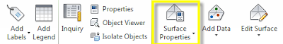
Surface housekeeping can be a bit time consuming if you don't know the tricks of the trade. I'm going to show you how to quickly cleanup and optimize your surfaces so that they are accurate and report accurate earthwork results. All of these setting options take place in the Surface Properties Dialog box. To access this click on your surface in your drawing space and then from your contextual ribbon select "Surface Properties".
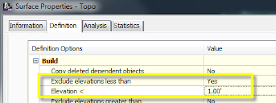
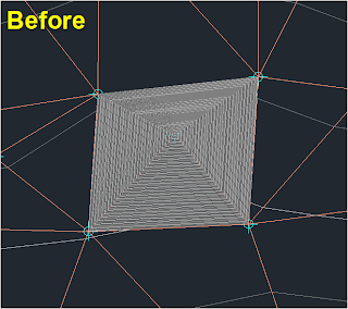
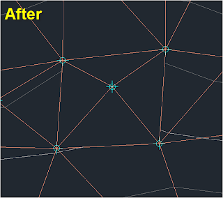
In the Surface properties dialog box select the "Definition" tab and then expand the "Build" category. We have 3 different settings we are going to look at. The first one is the "Exclude elevations less than" option. This option will control those points that have been added to the surface definition but don't contain a value (eliminating those "0" spikes from our surfaces). Doing this will resolve most black holes in the contours and result in more accurate earthwork calculations. Set the value for "Exclude elevations less than" to "YES" and then in the "Elevation" value just below enter "1".
Next we will look at "Using a Maximum Triangle Length". This one will require you to look at your surface data to determine the best value for your project. Do a couple of quick measurements to check the approximate topo grid shot spacing in your data and then choose a maximum triangle length that exceeds the longest value. This may take some trial to get the correct value and although it will not remove all the extraneous triangles it will remove a majority. This is very handy in the event you don't have a surface boundary to add to the definition. In the Same dialog box set the "Use a maximum triangle length" to "YES" then below that input the maximum value you determined in the last step.
And lastly lets take a look at the newest option added to the 2013 release. "Maximum angle between adjacent TIN lines" This option will in most cases resolve the remaining extraneous triangle lines in your surface. Again based on your data you may need to do a little trial on this to get the correct value. Set the "Use maximum angle" value to "YES" and then in the angle value just below enter your value (180 is the default).
Happy Surfacing!


